- Controller

- DC-Servo-Drive, 24V, 48V, 180V
- BL-Servo-Drive 12V, 24V, 48V, 90V, 180V
- BL-Servo-Drive 230Vac
- BL-Servo-Drive 400Vac, 480Vac
- Servo-Drive for Harsh Environments
- Stepper Motor Amplifier, 24V, 48V
- CAN-Interfaces
- CAN-Data-Loggers
- CAN-Cloud-Interface
- Automotive Ethernet
- Servo Accessories
- Control Circuits for Solenoids
- Motors
- Actuators
- Electromechanics
push/pull solenoids
tubular solenoids
superstroke tubular solenoids
open frame solenoids
latching solenoids
PUSH/PULL SOLENOIDS (SPP/PP)
The "Push/Pull" solenoids and "Small Push/Pull" solenoids of Geeplus are typical on/off linear actuators; they feature the most robust series of linear solenoids and are well suited for "heavy duty" applications. Their intelligent magnetical design allows high holding force at a comparably low current. Therefore push pull solenoids are ideal actuators for applications for which power consumption and heat dissipation are critical. They are called "Push/Pull" because both shaft ends are available, so the solenoid can be used as pushing solenoid or pulling solenoid, depending which shaft end is used for mechanical connection - but because of reluctance working principle the active moving direction when powering the coil is only unidirectional. Applications can be found in medical, laboratory and analytical equipment, e.g. in electrical pinch valves or in optical or semiconductor industry and lock applications.
We differentiate between "Small Push/Pull" and "Push/Pull" solenoids; the difference is related to the size and the mounting concept ("Small Push/Pull" use threaded holes in the base plate, "Push/Pull" have mounting studs). In the Push/Pull version there are two pole piece versions: flat for short stroke and high holding force, conical for longer stroke and higher starting force.
The following principal characteristics can be listed for (Small) Push/Pull solenoids:
- stroke up to 30mm (depending on type)
- holding force up to 2,000N (in end position, energized)
- can be used as push-type or pull-type linear solenoid
- high lifetime: up to 50 million cycles and more
- fast response time: switching time < 5ms possible (depending on size)
- standard sizes from 11mm to 874mm diameter
Especially for the short stroke push/pull solenoids it is possible to overcome the disadvantages coming from a very steep force stroke characteristic by using intelligent power electronics like Pick&Hold-Circuits. This allows very often to use a smaller linear solenoid or to reduce the heat dissipation of the push/pull solenoid in a specific application.


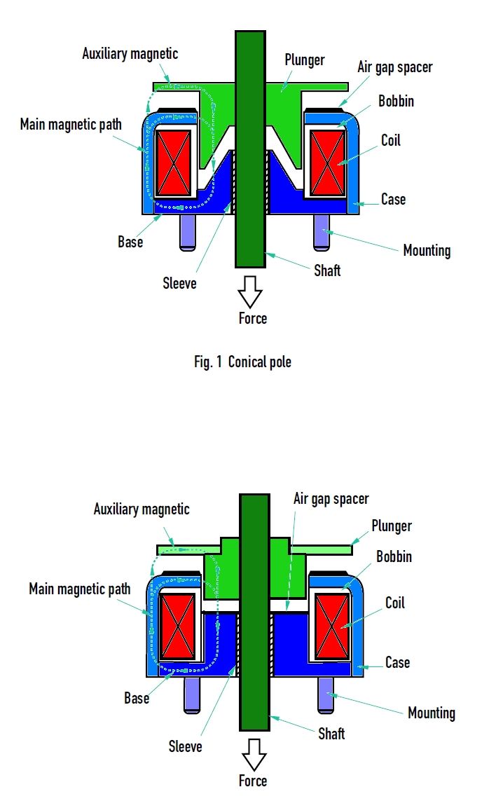 Push/Pull Linear Solenoid sectional picture
| "Push-Pull" solenoids | |||||||
| model | stroke mm |
holding force N |
dimensions mm |
mass g |
data sheet |
drawing 3D |
|
| 10% ED* | 100%ED* | d x h | total / plunger | .igs | |||
| 191C | 4 | 18 | 10 | 19.3 x 13 | 22 / 4 |
 |
 |
| 191F | 3 | 40 | 17 | 22 / 4 |
|
|
|
| 250C | 5 | 31 | 16 | 25.5 x 15.5 | 47 / 11 |
|
|
| 250F | 3 | 62 | 22 | 47 / 9 |
|
|
|
| 301C | 6 | 60 | 30 | 30 x 15 | 56 / 16 |
|
|
| 301F | 3 | 140 | 60 | 56 / 14 |
|
|
|
| 341C | 6 | 80 | 40 | 34 x 18 | 97 / 23 |
|
|
| 341F | 3 | 200 | 120 | 97 / 16 |
|
|
|
| 401C | 6 | 110 | 60 | 40 x 22 | 200 / 60 |
|
|
| 401F | 3 | 300 | 190 | 200 / 40 |
|
|
|
| 490F | 6 | 490 | 300 | 49 x 23 | 250 / 56 |
|
|
| 491C | 6 | 190 | 100 | 49 x 28 | 265 / 70 |
|
|
| 491F | 3 | 490 | 320 | 265 / 60 |
|
|
|
| 590C | 12 | 310 | 200 | 59 x 30 | 506 / 120 |
|
|
| 590F | 6 | 750 | 500 | 506 / 95 |
|
|
|
| 591C | 12 | 320 | 200 | 59 x 36 | 620 / 145 |
|
|
| 591F | 6 | 780 | 550 | 620 / 140 |
|
|
|
| 700C | 12 | 500 | 300 | 70 x 38 | 1013 / 268 |
|
|
| 700F | 10 | 1000 | 650 | 1013 / 285 |
|
|
|
| 870C | 14 | 850 | 500 | 87 x 47 | 1885 / 495 |
|
|
| 870F | 10 | 2000 | 1200 | 1885 / 480 |
|
|
|
| 874C | 30 | 950 | 650 | 87 x 82 | 3000 / 500 |
|
|
| 874F | 14 | 2000 | 1400 | 3000 / 535 |
|
|
|
*ED = relative on time (pay attention on max on time per cycle!)
| "Small Push-Pull" solenoids | |||||||
| model | stroke mm |
holding force N |
dimensions mm |
mass g |
data sheet |
drawing 3D |
|
| 10% ED* | 100%ED* | d x h | total / plunger | .igs | |||
| 110C | 2 | 4.5 | 1.5 | 11.3 x 13.3 | 7 / 1 |
|
|
| 141C | 3 | 15 | 5 | 13.8 x 13.7 | 12 / 2.5 |
|
|
| 144C | 5 | 12 | 6 | 13.8 x 21 | 18 / 3 |
|
|
| 190C | 4 | 15 | 5.5 | 19.3 x 13 | 20 / 4 |
|
|
| 192C | 4 | 20 | 10 | 19.3 x 17.5 | 27 / 4.5 |
|
|
| 194C | 5 | 25 | 18 | 19.3 x 26.4 | 44 / 9 |
|
|
| 221C | 5 | 23 | 12 | 22.3 x 17.5 | 39 / 9 |
|
|
| 224C | 6 | 35 | 21 | 22.3 x 28 | 63 / 12 |
|
|
| 251C | 5 | 35 | 15 | 25.5 x 15 | 47 / 11 |
|
|
| 300C | 5 | 45 | 18 | 30 x 15 | 58 / 16 |
|
|
| 304C | 5 | 55 | 32 | 30 x 21 | 79 / 15 |
|
|
*ED = relative on time (pay attention on max. on time per cycle!)
TUBULAR SOLENOIDS (T)
Tubular solenoids are on/of-type linear solenoids and provide fairly flat force stroke characteristics due to their tubular shape and their plunger geometry; they are well suited for applications asking for long strokes but not highest forces.
The principal characteristics of our tubular solenoids:
- stroke up to 30mm (depending on type)
- optimized for long strokes
- holding force up to 80N (in end position, energized)
- high lifetime: up to >30 million cycles
- standard versions with 13 to 38mm diameter
- pull type and push type tubular solenoids available


| " Tubular" solenoids | ||||||||
| model | stroke mm |
holding force N |
dimensions mm |
mass g |
data sheet |
drawing 3D |
||
| 10% ED* | 100%ED* | d x h | total | plunger | .igs | |||
| 133-L | 3 | 5 | 0.4 | 13 x 12 | 15 | 4 |
|
|
| 133-H | 3 | 5 | 0.4 | 13 x 12 | 15 | 2 |
|
|
| 130-L | 12 | 6 | 2.5 | 13 x 27 | 24 | 5 |
|
|
| 130-H | 12 | 6 | 2.5 | 13 x 27 | 24 | 4 |
|
|
| 170-L | 12 | 7 | 3.5 | 17 x 27 | 39 | 5 |
|
|
| 170-H | 12 | 7 | 3.5 | 17 x 27 | 39 | 4 |
|
|
| 190-L | 12 | 18 | 8 | 19 x 40 | 82 | 20 |
|
|
| 190-H | 12 | 18 | 8 | 19 x 40 | 82 | 16 |
|
|
| 253-L | 12 | 35 | 9 | 25 x 30 | 125 | 32 |
|
|
| 253-H | 12 | 35 | 9 | 25 x 30 | 125 | 19 |
|
|
| 250-L | 14 | 38 | 18 | 25 x 51 | 188 | 44 |
|
|
| 250-H | 14 | 38 | 18 | 25 x 51 | 188 | 35 |
|
|
| 320-L | 16 | 60 | 35 | 32 x 58 | 299 | 54 |
|
|
| 320-H | 16 | 60 | 35 | 32 x 58 | 299 | 53 |
|
|
| 380-L | 30 | 80 | 55 | 38 x 64 | 497 | 95 |
|
|
| 380-H | 15 (30) | 80 | 55 | 38 x 64 | 497 | 95 |
|
|
*ED = relative on time (pay attention on max. on time per cycle!)
SUPER STROKE TUBULAR SOLENOID FOR SEMI PROPORTIONAL CONTROL (SS)
The Super-Stroke-Tubular-Solenoids are linear solenoids with a super flat characteristics of force to stroke for a quite long part of their stroke; this allows them to be used as cost effective electrical linear cylinders for many applications requiring proportional control; they can be used as a replacement for many pneumatic cylinder. Another positive feature of the Super-Stroke-Tubular-Solenoids is controllable impact force. The advantage of the Super-Stroke-Tubular-Solenoids as a miniature electrical cylinder for e.g. 12V oder 24V over linear pneumatic cylinder is the quiet operation and the easy installation because they don't need any air supply.
The principal data of our Super-Stroke-Tubular-Solenoids:
- stroke up to 35mm (depending on type)
- opmtimized for long stroke
- holding force up to 24N (in end position, energized)
- high life time: up to >30 million cycles
- low noise (quiet operation)
- controllable impact
- standard sizes from 19mm to 38mm diameter
Watch this video to learn more about how a Super-Stroke-Solenoid works.

| "Super-Stroke-Tubular" solenoids | ||||||||
| model | stroke mm |
holding force N |
dimensions mm |
mass g |
data sheet |
drawing 3D |
||
| 10% ED* | 100%ED* | d x h | total | plunger | .igs | |||
| 190SS | 20 | 6 | 2 | 19 x 49 | 81 | 20 |
|
|
| 250SS | 32 | 13 | 3 | 25.4 x 81.5 | 200 | 46 |
|
|
| 320SS | 32 | 21 | 6 | 32 x 90.5 | 335 | 69 |
|
|
| 380SS | 35 | 68 | 9 | 38 x 84 | 535 | 91 |
|
|
OPEN FRAME SOLENOIDS (SK/TO/RD)
Open Frame Solenoids are the most cost-effective version of linear solenoids. Most of the open frame solenoids are comparably small, so they are considered as miniature linear solenoids. They are used in all kind of applications, which causes a wide spread of requirements regarding quantity, delivery time, quality and last but not least price. That's why we work with three production lines with different manufacturing equipment and locations. The according product families have their own profile for specific market segments.
General characteristics of Open Frame Solenoids:
- stroke up to 15mm (depending on type)
- holding force up to 30N (in end position, energized)
- life time up to 5 million cycles
- miniature versions: standard versions from 8 x 10 x 15mm
- many mechanical options, including return springs
- pull and push versions available
- rapid delivery service for RD series (4 weeks, even for custom linear solenoids)


| SK series | TO series | RD series | |
| price | most expensive | cost-effective for large series | cost-effective for lower quantities |
| delivery time | 8-10 weeks | 8-10 weeks | <3-4 weeks ex factory for quantities up to 10k |
| lifetime | >500k cycles | >500k cycles | >500k cycles |
| quality | outstanding | good | good |
| customized models | from 500 pieces | from 500 pieces | from 500 pieces |
| "Open Frame" solenoids | ||||||||
| model | stroke mm |
holding force N |
dimensions mm |
mass g |
data sheet |
drawing 3D |
||
| 10% ED* | 100%ED* | l x w x h | total | plunger | .igs | |||
| RD-A420 | 7 | 2.5 | 0.5 | 21.4 x 10.8 x 9.8 | 12 | 2 |
|
|
| RD-B425 | 7 | 2.5 | 0.9 | 25 x 12 x 10 | 16 | 3 |
|
|
| RD-A520 | 7 | 5.0 | 1.2 | 20 x 15 x 13 | 20 | 3 |
|
|
| RD-U617 | 7 | 3.5 | 0.7 | 17 x 18 x 19 | 25 | 4 |
|
|
| RD-A622 | 12 | 4.5 | 1.0 | 21.5 x 18 x 14 | 26 | 5 |
|
|
| RD-S622 | 14 | 4.5 | 0.6 | 21.5 x 18 x 14 | 26 | 6 |
|
|
| RD-A625 | 14 | 4.5 | 1.3 | 25 x 20 x 16 | 39 | 5 |
|
STP-File |
| RD-A628 | 16 | 4.9 | 1.5 | 28 x 20 x 16 | 43 | 6 |
|
|
| RD-B630 | 7 | 8.0 | 2.0 | 31 x 15 x 13 | 29 | 6 |
|
|
| RD-U630 | 16 | 4.2 | 1.5 | 30 x 20 x 15 | 42 | 6 |
|
|
| RD-U640 | 16 | 3.7 | 1.1 | 40 x 20 x 15 | 44 | 8 |
|
|
| RD-A730 | 16 | 6.0 | 1.4 | 30 x 16 x 14 | 32 | 9 |
|
|
| RD-A732 | 16 | 9.9 | 3.1 | 32 x 21 x 16.5 | 53 | 9 |
|
STP-File |
| RD-A840 | 16 | 13.5 | 5.0 | 36.8 x 26 x 20 | 83 | 12 |
|
STP-File |
| RD-B840 | 16 | 9.0 | 3.0 | 40.8 x 19 x 14.5 | 58 | 14 |
|
|
| RD-A940 | 16 | 16.0 | 5.1 | 36.8 x 26 x 20 | 85 | 16 |
|
|
| RD-B945 | 16 | 14.0 | 6.0 | 46.5 x 23 x 19 | 98 | 20 |
|
|
| RD-A1040 | 16 | 18.2 | 7.1 | 40 x 29 x 24 | 129 | 22 |
|
|
| RD-A1053 | 16 | 22 | 10.1 | 53 x 30 x 27 | 194 | 29 |
|
STP-File |
| RD-A1250 | 16 | 31.0 | 15.0 | 50 x 40 x 36 | 319 | 38 |
|
STP-File |
| RD-A1264 | 16 | 28.0 | 14.0 | 64 x 38 x 30 | 337 | 49 |
|
|
| SK-A0315 | 2 | 1.9 | 0.4 | 15 x 11 x 8 | 5 | 1 |
|
|
| SK-F0420 | 6 | 2.2 | 0.3 | 20 x 11 x 7.5 | 8 | 2 |
|
|
| SK-A0520 | 6 | 6.9 | 2.0 | 21 x 17.8 x 14 | 22 | 4 |
|
|
| SK-A0626 | 6 | 11.0 | 4.8 | 26.8 x 20 x 16 | 43 | 7 |
|
STP-File |
| SK-C0640 | 6 | 9.1 | 4.1 | 40 x 20 x 13.5 | 48 | 9 |
|
|
| SK-A0730 | 6 | 14.2 | 5.1 | 30.3 x 20 x 16 | 48 | 8 |
|
|
| SK-A0832 | 6 | 20.1 | 9.9 | 33 x 26 x 22 | 82 | 14 |
|
|
| SK-W0836 | 6 | 23.0 | 10.0 | 37 x 26 x 20 | 100 | 14 |
|
STP-File |
| SK-A0946 | 6 | 22.0 | 10.1 | 46.5 x 23 x 19 | 96 | 20 |
|
|
| SK-A1040 | 6 | 31.0 | 13.0 | 40 x 29 x 24 | 126 | 23 |
|
|
| SK-W1250 | 6 | 54.0 | 28.5 | 50 x 40 x 36 | 362 | 40 |
|
|
OPEN FRAME LATCHING SOLENOIDS (SH1LC/R1L/T1L/SH2LC/T2L/TK2L)
Latching solenoids are Open Frame Solenoids with a permanent magnet which provides a self holding function in one or both endpositions with no current applied; there are latching solenoids with one coil which show the self-holding function when the plunger is pulled into the housing; with an additional return spring a sedond holding position can be achieved by the spring (plunger pushed out of the housing); but you have to be aware that the characteristics of this solenoid are not symmetrical per direction and that also the current for pulling in and release are different. In case an identical behaviour of the solenoid in both directions is required in the application, a different construction with two coils and a central permanent magnet between those two coils is needed; the disadvantage of the two coil version of latching solenoids is the fixed stroke defined by the size and geometry of the particular latching solenoid and the general limitation of stroke (up to about 5mm).
Also latching solenoids are mostly quite small in general; Geeplus offers special miniature latching solenoids which are used e.g. in cameras as shutter actuators.
The principal data of our latching solenoids:
- stroke up to 15mm (depending on type)
- holding force up to >36N (in end position, de-energized (no current))
- bistable versions available (dual coil latching solenoids)
- zero power consumption for holding, therefore zero heat dissipation in holding position
- special versions for higher actuation force (lower holding force): Leakage Pole Type latching solenoids
- lifetime up to >5 million cycles
- miniature versions: standard dimension from 4 x 8 x 15mm, custom designs even smaller!
- many mechanical options


| " Open Frame Latching" solenoids | ||||||||
| model | stroke mm |
holding force N |
dimensions mm |
mass g |
data sheet |
drawing 3D |
||
| only magnet* | 10%ED* | w x h x l | total | plunger | .igs | |||
| S1L-0211 | 2 | 2.5 | 1.5 | 6.2 x 6.5 x 14 | 1.4 | 0.3 |
|
|
| SH1LC-0524 | 5 | 2 | 3 | 12 x 10 x 24 | 14 | 3.1 |
|
|
| SH1LC-0730 | 5 | 5 | 10 | 16 x 15 x 30 | 38 |
|
||
| SH1LC-1140 | 7 | 12 | 44 | 26.5 x 23 x 40 | 120 | 28.1 |
|
|
| SH1LC-1240 | 7 | 20 | 50 | 29.5 x 25 x 40 | 145 | 33.8 |
|
|
| SH1LF-0524 | 5 | 2 | 5 | 12 x 10 x 24 | 14 | 3.1 |
|
|
| SH1LF-0730 | 5 | 9 | 20 | 16 x 15 x 30 | 38 | 9.4 |
|
|
| SH1LF-1140 | 7 | 16 | 60 | 26.5 x 23 x 40 | 120 | 28.1 |
|
|
| SH1LF-1240 | 7 | 26.5 | 80 | 29.5 x 25 x 40 | 145 | 33.8 | |
STP-File |
| SH2LC-0524 | 2 | - | 1.9 | 12 x 10 x 36 | 15 | 3 |
|
|
| SH2LC-0730 | 3 | - | - | 17 x 15 x 51 | 35 | 7 |
|
|
| SH2LC-1140 | 4 | - | - | 25.5 x 23 x 66 | 115 | 21 |
|
|
| T1L-0420 | 5 | 1 | 2 | 13 x 10.5 x 20 | 12.3 | 1.7 |
|
|
| T1L-0421 | 5 | 2 | 2 | 11 x 8.5 x 20.5 | 10 | 1.7 |
|
|
| T1L-0422 | 5 | 1.8 | 2 | 11 x 8.5 x 22 | 10 | 2 |
|
|
| T1L-0625 | 7 | 8 | 9 | 15 x 13 x 25 | 25.7 | 4.6 |
|
|
| T1L-0730 | 7 | 8 | 9 | 16 x 14 x 30 | 34 | 7.8 |
|
|
| T1L-0742 | 7 | 7 | 12 | 20 x 16 x 42 | 58 | 9.9 |
|
|
| T1L-1037 | 12 | 19 | 20 | 26 x 20 x 36.8 | 95 | 18.3 |
|
|
| T1L-1240 | 14 | 23 | 40 | 29 x 24 x 40 | 133 | 31.1 |
|
|
| T1L-1253 | 14 | 36 | 48 | 30 x 27 x 53 | 211 | 43 |
|
|
| RD2L-0932 (bistabil) | 6 | 40 | 20 (5%) | 25 x 25 x 32 | 86 |
|
||
 PRINT PAGE |